|
CAPE HENRY 21 PHOTOS
These pages show a mixture of CC19 and CH21 photos. Construction of the two designs is almost identical, so builders of each design will benefit from photos of the other.
Building 1 - Hull skeleton
Building 2 - Centreplate case, hull bottom
Building 3 - Completion of hull
Building 4 - Interior Joinery
Building 5 - Deck Construction
Building 6 - Deck Finishing
Building 7 - Deck Fittings
Building 8 - Completed Interior
Building 9 - Completion
Amateur projects - Photos & web links
More links to amateur projects
Cape Cutter 19 Sailing Photos
Cape Henry 21 Sailing Photos
Videos
1 ~ DECK STRINGER END SUPPORTS
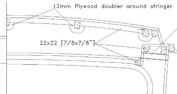
The ends of the deck stringers must be supported where they run out against bulkheads 2 and B. This is most easily done by cutting U-shape brackets from 12mm plywood and bonding each to the bulkhead face to form a socket in which the stringer end can be bonded. Fit 22x22mm [7/8x7/8"] square cleats against the bulkheads between the stringers to form a landing for the plywood deck.
The diagram below shows how this works on bulkhead 2. The same principle applies at bulkhead B. Similar doublers can be used to house the ends of berth supports and other joinery frames where they terminate against bulkheads.

2 ~ TRANSOM RADIUS
The intended transom radius is shown on the lines drawing. This is the curvature for the outside of the transom. The transom and its doublers must be laminated over a temporary wooden mould shaped to the curve of the inside of the transom doublers, ie the transom and doubler thicknesses must be subtracted from the radius shown when building the mould. The internal cut-outs from the doublers should be fastened to the mould as well but not glued to the transom. These will support the transom across the cutouts and ensure a more uniform curvature when the transom is removed from the mould.
There will be some springback (straightening) of the laminated transom/doubler structure. It can be held to the intended shape by screwing two temporary curved frames to the inside or outside. These can be removed when the transom is restained by the hull and cockpit
3 ~ BUILDERS' FORUM
There is an active builders discussion forum on Yahoo groups for builders of the Cape Henry 21. The address is http://groups.yahoo.com/group/capehenry/. You will need to register with Yahoo Groups to enter the forum. The issues discussed will be useful to builders of plywood Cape Cutter 19s as well.
4 ~ BULKHEAD A CORRECTION
We have found a small error in the shape of the bottom panel of Bulkhead A as shown on patterns and kits supplied prior to May 10th 2004. The diagram below shows how to correct the error by gluing a wedge of plywood or timber onto the edge of the bulkhead. The wedge is 7mm thick at the backbone and tapers to 0mm at the chine. In the diagram below the red lines show the original shape of the bulkhead and the blue lines show what it must be changed to. The stringer slot must also be adjusted to the new surface.
The backbone has extra width to allow for the changing bevel angle that must be planed to suit the twist of the bottom skin angle. Establish this angle by making a saw cut into the backbone as an extension of the bulkhead edge from both sides. Cut the backbone down to the intersection of the two cuts made at each bulkhead and use them as a guide for trimming the backbone to width and angle.

5 ~ SPACERS TO CENTREPLATE SLOT
Bill Empsall in NY has found that the centreplate case closes a bit under pressure from the bottom panels when these are being fitted. He recommends that a couple of temporary spacers be fitted into the slot to keep it at the correct width until the epoxy fillets can be done. Thanks Bill, for that tip.
6 ~ DOUBLERS TO BACKBONE IN BOW
The backbone needs to be locally increased in width at the U-bolt for the bobstay. Do this by adding extra layers of plywood between chine 1 and DWL in the same way as shown in "Bow Section at Sheer" on the construction drawing.
Some builders have reported too much flexibility in the backbone in the lower bow area when building. This bends when applying pressure to it during fitting of the forward bottom panels. There are two possible ways to compensate for this during building.
A) Clamp temporary stiffener/s to the backbone between A and 2 to hold it straight while fitting the bow bottom panels.
B) Fit a permanent 10mm plywood doubler each side between Bulkheads A and 2.
7 ~ BOTTOM SKIN IN BOW
There is a lot of twist to the bow bottom panels in the forefoot area. Don't try to skin this in full length plywood sheets. Break it into 2 or 3 lengths to reduce the strain in the plywood. If building with okoume plywood, 2 lengths will do it. If building with meranti or mahogany plywood, 3 lengths will be needed because of the greater stiffness of the sheet.
Builders in UK have had no problems fitting these panels, without breaking them down into shorter lengths. They are using okoume plywood, which makes a big difference. They also soften the plywood with water to help it. One builder used a steam wallpaper stripper to steam the sheets during fitting, which proved very effective.
8 ~ BOWSPRIT DETAILS
There is a dimension error on drawing No 15. The dimension "1240mm to tip of bow" should read "1364mm to tip of bow".
The bowsprit is to be solid timber (Douglas fir or similar) 82x82mm finished size and 2250mm long. Make the aft 100mm octagonal to fit the heel fitting and the 700mm forward of that can either be 82x82mm octagonal or round to suit your own likes. Forward of this it must be tapered down to the 51mm tip size shown on drawing No 15. The tapered section can also be either octagonal or round.
9 ~ CENTREPLATE CASING TOLERANCES
An amateur building a plywood Cape Cutter 19 in UK reported that when he came to fit the centreplate it would not fit into the slot. This resulated from a combination of generous epoxy/graphite coatings inside the casing, galvanising thickness on the plate and distortion in the plate and casing. Please watch your tolerances during construction to ensure that the plate will fit the slot when complete.
10 ~ BALLAST WEIGHTS
Internal ballast weights shown on the drawings for lead shot ballast are for the total weight of the lead and epoxy. Using lead shot of uniform particle size, the weight of lead shot should be 97% of the total weight and the epoxy should be the remaining 3% of the total.
11 ~ CENTREPLATE LIFTING MECHANISM
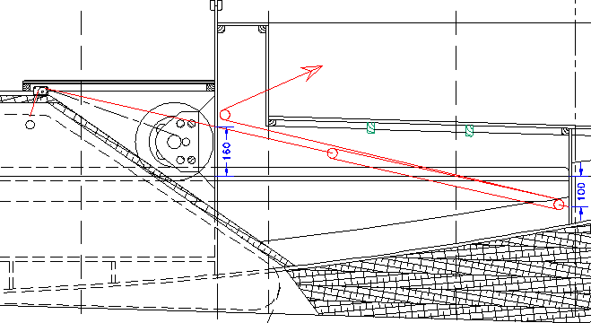
The drawings show a winch mechanism for lifting the centreplate. An alternative is to fit a tackle, which needs to be at least 6:1 and can fit between the exit point of the cable and Bulkhead C. Anchor it on centreline 100mm below DWL on Bulkhead C, with the cable passing through Bulkhead B via a hole centred 160mm above DWL. The travel needed is 600mm (24"), so the tackle can be between Bulkheads B and C, with only the cable passing through Bulkhead B. The tail of the rope can be run through a block attached to the aft face of Bulkhead B to turn it aft so that it can pass through the front of the cockpit to a cleat. See the diagram below for clarification.
Use Ronstan Series 40 blocks, which are the smallest that will take the 3/8" line. Use RF40302 (triple block) on the aft end of the strop, RF40312 (triple block with becket) on the aft bulkhead, RF40101 (single block) on the forward bulkhead and RF41712 sheave box on top of the casing.
For the Cape Cutter 19, instead of the 100mm and 160mm dimensions, use 90mm and 145mm respectively.

Back to Cape Cutter 19 page
Back to Cape Henry 21 page
|